Agen judi togel online memiliki tujuan untuk mensejahterakan masyarakat Indonesia dengan kemampuan kami menjadi wadah penampung para pecinta permainan bersejarah satu ini. Untuk kamu yang memang sedang berada di tengah krisis ekonomi keluarga, tentu saja kamu harus mencari cara karena memang kamulah pencari nafkah untuk istri dan anakmu. Di sinilah peran kami sebagai agen togel terpercaya dan terbaik di Indonesia, untuk membantu kamu menjadi ayah yang bertanggung jawab.
Menjadi ayah yang bertanggung jawab memang bukan hal mudah, maka dari itu, agen judi togel online terpercaya seperti kami inilah yang bisa menjadi jawaban kamu. Calon bettor tidak perlu pusing-pusing lagi dengan krisis finansial yang melanda keluarga kamu. Apalagi jika anak kamu hendak masuk ke pendidikan pertamanya yaitu Taman Kanak-kanak. Pasti kamu butuh banget kan cuan tambahan dari bermain togel online bersama kita?
4 Keuntungan Bettor Baru yang Gabung Agen Judi Togel Online

Untuk kamu yang memang sudah memantapkan diri dan ingin segera mendaftarkan diri bersama agen judi togel online, memang sekaranglah waktunya guys. Apalagi registrasi bersama kami tidak mengeluarkan sepeser pun yakni daftar gratis.
Maka dari itu, kamu jangan ragu guys, karena tidak ada ruginya kok daftar akun di agen judi togel online bersama kami. Yuk kulik 4 keuntungan bettor baru yang baru saja mendaftarkan diri bersama kami.
- Daftarnya cepat
Selain gratis, proses daftar akun baru bersama kami sangatlah cepat. Bahkan seperti hanya membalikkan telapak tangan saja, langsung deh punya akun baru. Hanya perlu masukin nomor HP kamu, lalu minta kode OTP, dan masukkan ke kolom yang tersedia. Setelah itu, akun baru kamu langsung login untuk pertama kalinya, tandanya sudah aktif tuh guys.
- Ada bonus modal awal
Lalu jika kamu langsung login untuk pertama kalinya ke akun yang baru saja kamu bikin, satu hal yang harus kamu tahu. Bahwa kami menyediakan bonus berupa modal awal untuk kamu bisa langsung memainkan semua jenis taruhan togel kami. Tentunya penasaran kan, apakah benar? Makanya cobain sendiri deh guys, kamu pasti langsung tercengang.
- Free spin setiap login
Jika bettor baru memang sering bermain bahkan hampir setiap hari login, tentu akan kami apresiasi. Sebagai agen resmi terpercaya togel online, kami memang apresiasi sekecil apa pun loyalitas yang kamu tunjukkan. Seperti login setiap hari, akan dapat free spin, yang mana bisa memberikan kamu sebuah bundling bonus yang menarik.
- Terdapat kode referral
Terakhir, keuntungan untuk kamu bettor baru gabung adalah kode referral yang harus kamu manfaatkan. Jika kamu memang memanfaatkan ini sangat menguntungkan banget sih. Bayangin, kamu berhasil mengundang orang daftar di agen kami akan dapat komisi sebesar 50 ribu per kepala.
Hadiah Harian dari Agen Judi Togel Online Terbaik untuk Kamu
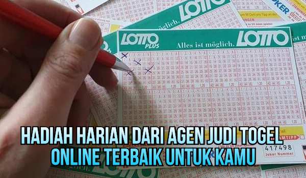
Keuntungan-keuntungan yang baru aja kamu baca di atas memang sudah pasti akan diberikan oleh agen judi togel online seperti kami. Namun ada beberapa bonus yang tidak tentu namun nominalnya tidak kalah menggiurkan. Bonus tersebut sistemnya harian yang memang kamu harus tahu formula untuk mendapatkannya.
Untuk bisa mendapatkan hadiah harian dari agen judi togel online terbaik bagi kamu yang baru saja daftar akun. Syaratnya sebenarnya hanya satu, kamu hanya perlu untuk login selama lima hari berturut-turut dan melakukan deposit gopay ke saldo akun togel kamu. Mudah banget kan? Nantinya akan ada hadiah menarik untuk kamu.
Kumpulan Pasaran Judi Togel Resmi Dan Terpercaya Sering Keuntungan Besar
Jika Anda sedang mencari situs terbaik dan terbesar di Indonesia, tentu situs judi togel terpercaya sangat tepat untuk Anda jadikan tempat bermain. Karena situs kami sudah mempunyai lisensi resmi dari lembaga perjudian Internasional sehingga tidak perlu diragukan lagi kualitas dan fasilitasnya. Tidak hanya itu, situs judi togel juga sudah memiliki ribuan pengikut yang akt8if bermain setiap harinya demi mendapatkan kemenangan sangat besar mencapai ratusan juta bahkan milyaran rupiah.
Tidak hanya itu, situs kami sudah selalu menyediakan pasaran judi togel terlengkap dan terpercaya sebagai berikut:
- Judi Togel Sering Kasih Keuntungan Besar Taiwan
- Judi Togel Sering Kasih Keuntungan Besar Jepang
- Judi Togel Sering Kasih Keuntungan Besar China
- Judi Togel Sering Kasih Keuntungan Besar Cambodia
- Judi Togel Sering Kasih Keuntungan Besar Mexico Lottery
- Judi Togel Sering Kasih Keuntungan Besar Singapura
- Judi Togel Sering Kasih Keuntungan Besar San Marino Lottery
- Judi Togel Sering Kasih Keuntungan Besar Sydney
- Judi Togel Sering Kasih Keuntungan Besar Hongkong
- Judi Togel Sering Kasih Keuntungan Besar Toto Macau